Convert Your Old Wired Home Alarm System into a DIY Smart Home Security System
Homes with existing alarm system wiring can provide your home automation system with a multitude of sensors. The problem to date is that there have not been really good options to take advantage of the wired sensors. Until today that is. In late 2018, Fibaro released the Smart Implant which is a Z-Wave plus device that can take a variety of sensor inputs and report those back to a smart home hub. It also has two outputs, which allows the hub to control either a power leg or ground leg of a 9-30 VDC circuit.

The video (and this article) walk through how to use the Fibaro Smart Implant FGBS-222 to connect your hard-wired alarm sensors into your Z-Wave hub.
Below is a link to an Amazon Storefront that contains useful items for this build. If you can find these items around your house, you in good shape. Some items may come in handy so you don’t have to go searching around.
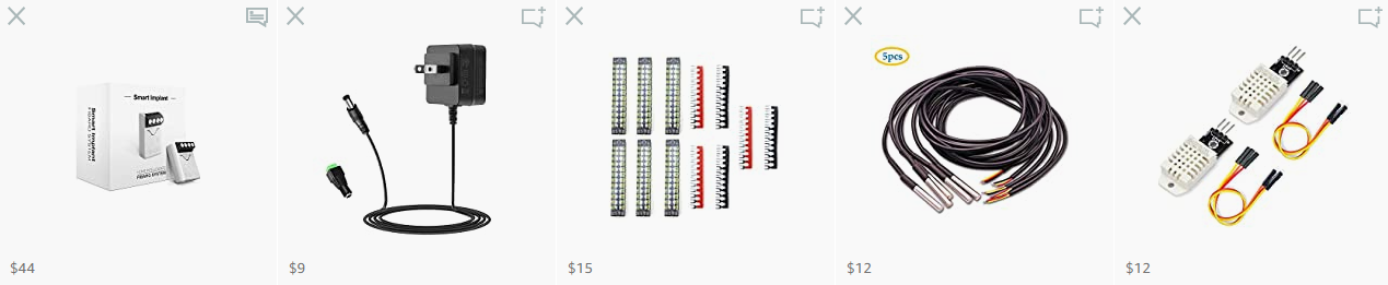 Full Build List on Amazon.com
Hub Compatibility
I only tried connecting the Fibaro Smart Implant on SmartThings, Hubitat Elevation, and Vera.
SmartThings
To get the Implant properly working with SmartThings you will need a set of custom device handlers, a total of six in all. I tried two different sets, the best I could find was from ovidiupruteanu. You’ll need to load those into your SmartThings account. The video describes how to interact with the device in the SmartThings app.
The device handlers include:
- fibaro-smart-implant.src
- fibaro-smart-implant-button.src
- fibaro-smart-implant-contact.src
- fibaro-smart-implant-dht22.src
- fibaro-smart-implant-ds18b20.src
- fibaro-smart-implant-switch.src
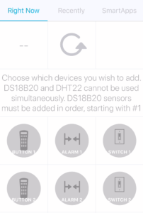
When the device comes into SmartThings, you will only see the parent device on the My Home page. This is because you haven’t configured any of the features as of yet. You’ll need to click on the parent device (Fibaro Smart Implant or whatever you named it) so get into the device details.
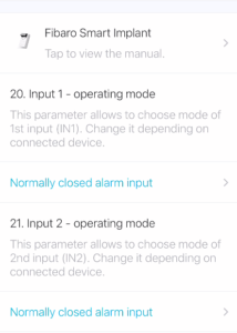
Once you’re on the device details page, nothing here will be working, try as you might. You’ll need to click the Gear Icon to get to the parameters page. Once there, set your contact sensor type to either Normally Open Alarm Input or Normally Closed Alarm Input, whichever you have.
- You’ll then save those settings, which will take you back to the device page.
- Press the Refresh icon to sync the settings.
- Go back to the My Home page.
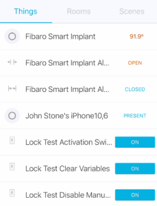
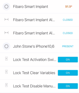
You’ll need to open and close the door or window to active the status.
NOTE: My normally closed sensors read backward in SmartThings. I’m not really sure why. But this is really not an issue. You can reverse the sensor type (in my case I registered my NC sensor as a Normally Open sensor and all was well.
Hubitat
To get the Implant properly working with SmartThings you will need a custom set of device handlers. The best I could find was from christi999 as a derivative of handlers originally created by muchu999. You’ll need to load those into Hubitat.
The device handlers include:
- Fibaro FBGS-222 Child Analog Input.groovy
- Fibaro FBGS-222 Child Digital Input.groovy
- Fibaro FBGS-222 Child Switch.groovy
- Fibaro FBGS-222 Child Temperature Sensor.groovy
- Fibaro FBGS-222 Smart Implant.groovy
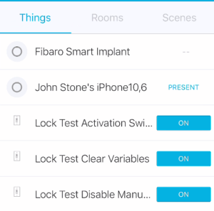
Pair the Fibaro Smart Implant after you install the handlers. After pairing the Implant, you should see a device that looks like this.
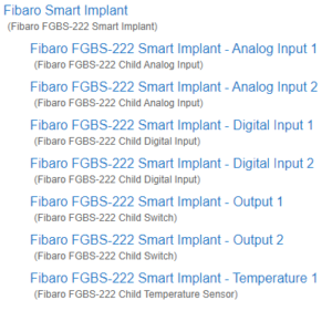
Fibaro Smart Implant in Hubitat
If you don’t see the child devices:
- Make sure the Implant is using the correct driver (sometimes it comes in as a device).
- Exclude and re-Include the Implant (this cleared it up for me).
It’s also a good idea to make sure you have other Z-Wave Plus constant powered devices nearby like an in-wall switch or a Z-Wave Plus Range Extender. As always, I’m a big fan of the Aeotec Range Extender.
 |
 |
| Aeotec Range Extender 6 | Aeotec Range Extender 7 |
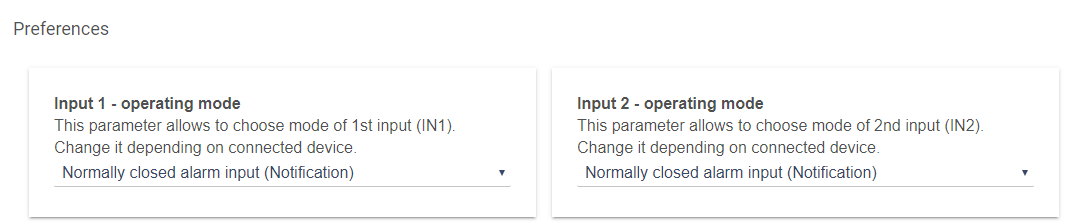
Once the device is in your hub, you will need to configure the settings for the contact switches. For each input that you use, you will need to set the operating mode. Use either the Normally Open or Normally Closed Alarm Input (depending on which style you have – usually normally closed). Once it’s in your hub, you can open and close the window or door to make sure you have it set correctly.
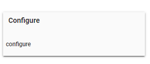
After you save the preferences, you need to press the Configure button to send the parameters to the Smart Implant.
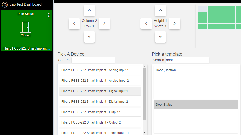
When you put the door or window sensor on a Dashboard, you’ll want to pick Digital Input 1 (or 2). This will make everything appear correctly.
Vera
I really tried to get this working on Vera. The way Vera handles device handlers is not as straight forward as it is on Hubitat and SmartThings (at least not for me). The best I can do is provide a link to a Vera Community article that other found successful. Hopefully, if your a Vera user, you’ll have more luck than I did.
Basic Wiring Setup
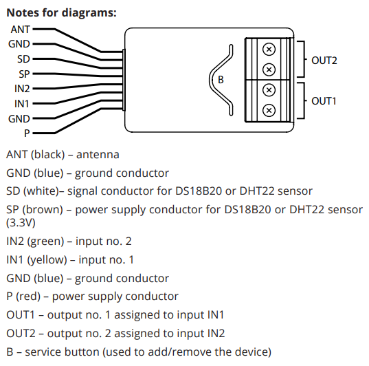
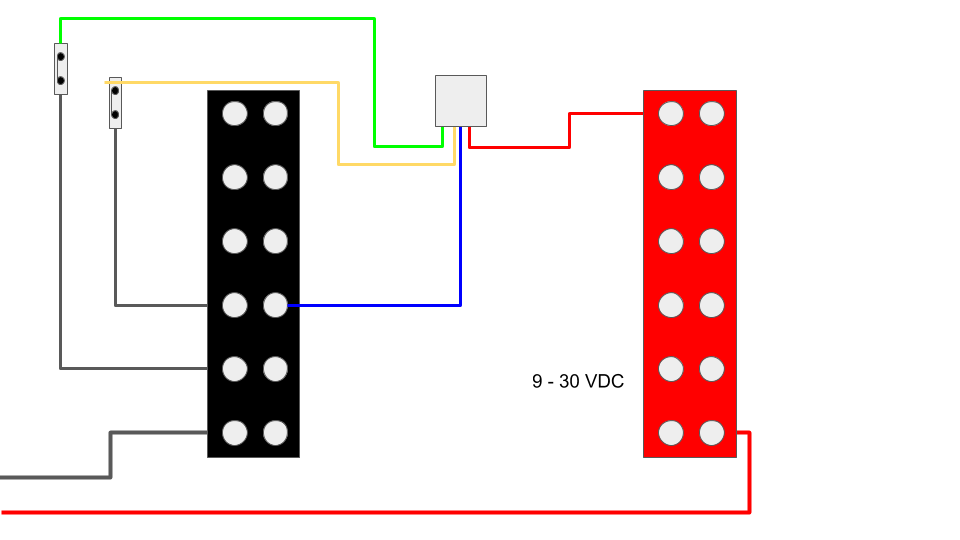
If you’re not interested in making this pretty, you can follow the diagram supplied in the Fibaro Smart Implant Manual. It still requires 9-30 VDC of power, so some of the supplies shown above may help. Here’s the wiring in a nutshell. You don’t need to use both inputs, but if you have several sensors that you are trying to wire in, the ability to wire in two comes in handy.
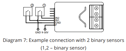
The wire colors are as follows:
Alarm Panel Conversion
In my case I wanted to make sure that the wiring stayed nice and neat in the panel. For this reason I chose to install terminal blocks in the old alarm panel. This allowed me to connect the power and ground to different bus-bars and make installation and maintenance a lot easier.
For the power, I started off with an old 12 VDC power supply. Once I tore into the alarm panel, I found a 14 VDC power supply which I ended up using. I used some lever nuts to clip connect the one leg of the wire that runs to the sensor, and the other leg of the sensor gets attached to the negative (black) side of the terminal strip. Lever nuts and terminal strips are on the Amazon Build List.
Isolating Alarm Wires
The hardest part of the installation is figuring out which wire goes to what. You’ll need some kind of multi-meter or continuity tester (also on the Amazon Build List) to help figure out what wire goes to what. Connect a pair of wires to the continuity tester and then go and open and close doors. This may require two people to speed it up. Otherwise you go and open a door, run back to the panel to see if that was it, and then close the door. Then move on to the next set of wires. Hopefully the installer marked them.
Beware of Series Circuits
In many cases, the installer may have opted to place multiple sensors into a single set of wires. This is usually done with Normally Closed contact sensors. This way if any door or window in the circuit get’s opened, the entire zone is broken at the same time tripping the alarm. This is most common with windows. Doors are ‘usually’ on their own circuit, but you never know what you will find. The diagram below shows the types of series circuits I encountered in my home.
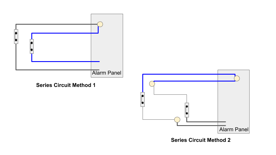
Method 1 is pretty straight forward and the easiest to figure out. Two sensors each with dedicated wiring. one leg of each wire is joined in the alarm panel. You can maintain this configuration to save the amount of smart implants you’ll need to complete your DIY alarm system.
Method 2 will blow your mind a little when your trying to figure out the wiring. The small thin wires run between the two contacts (different windows). You’ll see one pair joined and the other pair looks normal. When you test for continuity across each pair, you’ll get unpredictable results (unless you understand the wiring).
If you run across other types of wiring, come let us know over on the Facebook Group and we’ll help you figure it out (if we can). Or if you figure it out, let me know (same place) and I’ll add the wiring to this page.
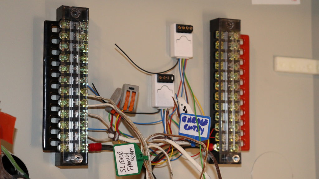
My Final Result
In the end, here’s what it looked like in my panel. I have several circuits to figure out and I have a few bad sensors that need replaced. But it’s a start.
END