Lock Testing and Error Rates
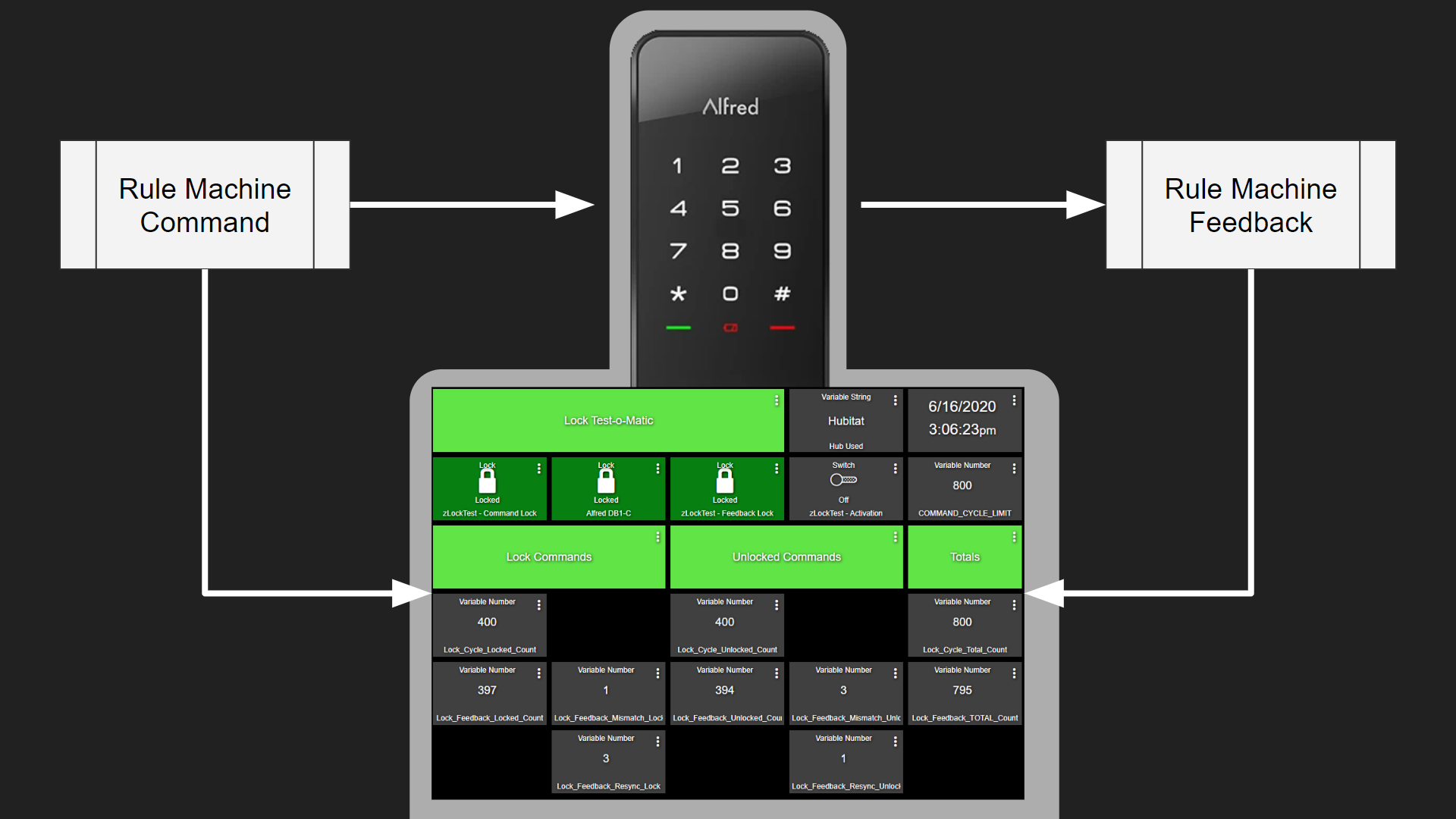
When it comes to testing smart locks, I focus on two aspects: 1) does the lock do what it’s told to do when commanded by the hub; and 2) does the lock tell the hub what happened (locked, unlocked, which user, etc.). My goal is for these tests to be as automated as possible. The more automated the tests, the more cycles can be put on the lock. The more cycles, the more the consumer can rely on the information.
It was for this reason I created my Lock Test-o-Matic which is a set of rules (described in detail at the bottom of this article) running in Hubitat Rule Machine.
Testing Across the Hubs
As of the time of this writing I am able to use this same process on Hubitat, SmartThings and Vera. All of the code in the Test-o-Matic runs locally in Hubitat. Testing in Hubitat is the easiest since that is where all of the Rule Machine logic resides.
To test in SmartThings, I’m using a user created app called HubConnect which allows me to use Hubitat as a ‘server’ hub and SmartThings as a ‘client’ hub. This setup allows selected devices in SmartThings to appear in Hubitat, which in turn means that Hubitat control the lock through Test-o-Matic as though it was a local lock. When testing in SmartThings I increase the time between commands to allow for the cloud connection between Hubitat and SmartThings.
Testing in Vera is more complex. HubConnect does not support Vera, so other means needed to be invented. Hubitat has a built-in app called Maker API, which allows data to be sent to and received from external web connections. As luck would have it, Vera has a similar feature called Universal Plug and Play (UPnP). I created (slightly) modified rules in Hubitat specifically for Vera that allow the Commands (discussed below in more detail) to be sent to a web server on my local network and my web server then sends the command to Vera. My server then queries Vera to see if the command was executed, and then sets the feedback accordingly in Hubitat. So, for the most part, Hubitat has no idea that the lock is not local, and Vera commands the lock as though all the logic was local to Vera.
Given these factors, it’s quite normal that my best results are usually with Hubitat, next best are with SmartThings, and Vera usually comes in last. These differences are usually within tenths of a percent (e.g. 99.2%, 98.7%, and 98.5% respectively). This is due to the fact that the Hubitat testing is the least complicated in terms of integrations, and Vera is the most complicated in terms of integrations.
In all cases it should be noted that there is so much going on with Test-o-Matic that the results should be taken with a grain of salt.
Test Accuracy
Test-o-Matic is a powerful tool, even with the faults. However, it does have a way to tell you how unreliable it is, mostly. I never just set the Test-o-Matic and walk away and then review the data. I generally run preliminary tests of 20 to 50 cycles and watch very closely to see how the lock is behaving with Test-o-Matic before I run longer tests to ensure the results are reliable. Therefore, the following information is assuming that I have already verified that the lock and Test-o-Matic are getting along.
There are three key metrics that provide the overall score: 1) success, 2) mismatch, and 3) missing data. Below is an overview of how those are used and there are better details later in the article.
Success
Success counts are probably the most reliable in that Test-o-Matic knows it sent a message (command) and that it received a message (feedback) that corresponded to the command. Feedback is only captured when the lock itself tells Test-o-Matic that the lock changed state. So the Success metric is the most reliable.
That said, Fail messages (or calculations) are unreliable for the following reasons.
Mismatch
As mismatch occurs when Test-o-Matic checks to see if the lock is in the predicted state. For example, before the lock gives a ‘Lock’ command, it checks to make sure the lock is ‘Unlocked’. If it is actually locked, it sets a mismatch error. This only checks the hubs understanding of the state, not the physical state of the lock. Either way there is a mismatch in what the hub thinks the lock state is, and what it is trying to do next.
A very common reason for a mismatch is the Test-o-Matic trying to run the commands too close together, which does not provide enough time for the lock feedback to register in the hub. However on locks that are just plain out crappy (with one or more hubs), this is probably telling us we should not trust the lock itself (at least with a hub that reports a high amount of mismatch counts).
Missing Data
It is not uncommon to get to the end of a test cycle and have the numbers not add up. For example, Test-o-Matic sends 100 Commands and receives 95 Success messages and 3 Mismatch messages. Adding Success and Mismatch should equal Commands. in this case, we are two short. This is missing data. I have no clue why this happens, but in my mind I blame it on the Test-o-Matic. I can’t assume that this is a Success or a Mismatch, so this is what becomes my margin of error. The data presents itself like this:
| Cycles | Locked Success | Locked Mismatch | Unlocked Success | Unlock Mismatch | Unknown Status | Reliability | Deviation |
| 100 | 48 | 2 | 47 | 1 | 2 | 96.00% | 1.00% |
The deviation column at the end is accounting for the 2 pieces of missing data and the commands that were given even when there was a resync (described in more detail later). If those missing pieces and resyncs where actually successes, the reliability would be 97%, and if they were failures, the reliability would be 95%. So my math takes the average of the highest possible success rating (97%) and the lowest (95%) and averages them, in this case 96%. This would mean the lock (on that given test) had a reliability of 96% +/- 1%.
Is Anything Less than 100% Bad?
Short answer: yes and no. As you can see, there are a lot of moving parts in my Test-o-Matic and it’s hard to say exactly how a lock will perform in your home or in a real scientific test. My experience testing locks (and other devices) tells me there is somewhat of a curve. So when I give star ratings, they are allocated as follows:
| Success Rate | Stars |
| 98.5% – 100% | |
| 97% – 98.4% | |
| 96% – 96.9% | |
| 92.5% – 95.9% | |
| 90% – 92.4% | |
| 87.5% – 89.9% | |
| 85% – 87.4% | |
| 82.5% – 82.4% | |
| 80% – 82.4% | |
| 70% – 79.9% | |
| < 70% |
Wan’t more help? Join the DIY Smart Home Guy Facebook Group! It’s the best place to ask questions and get help on topics covered in my videos and on my website. There are lot’s of other smart people there as well. If I can’t help, maybe someone else can. Give it a shot. |
Command Cycles
Test-o-Matic is set to send the desired amount of commands. Generally, I try to send 1000 cycles to the lock (500 lock, 500 unlock) from Hubitat to get a baseline. I use Hubitat as the baseline since that is where Test-o-Matic runs. As mentioned before, SmartThings brings in HubConnect, and Vera brings in my web server, Maker API and UPnP, so there are more things that can go wrong. Hubitat, in my case, is the best way to get a good baseline. As stated earlier, this is why it’s common for Hubitat testing to perform better than SmartThings and Vera testing.
- If all hubs report essentially the same results, it can be assumed that the lock performs the same regardless of the hub (good or bad).
- If there are errors detected and one hub outperforms another hub, the issue is most likely with the hub device driver. Although I have seen locks misbehave on one hub and the root cause was the lock firmware.
- If errors are detected equally across all hubs tested, the issues are most likely with the lock itself.
These tests are not scientific, but they do provide a consistent testing method to help determine lock reliability and/or hub performance with a particular lock model.
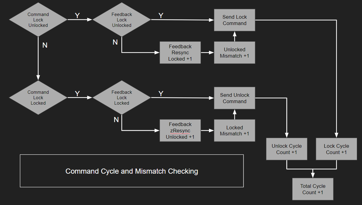
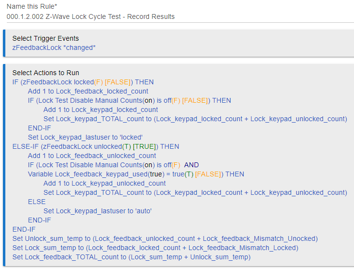
Figure 1 – Lock Cycle Command Logic
Mismatch Detection
As shown in Figure 1 above, before a lock or unlock command is given, the logic first determines if there is a mismatch between the last lock command and the last feedback provided. If there is a mismatch, the mismatch is recorded as a Mismatch Count (for either lock or unlock), a Re-sync is recorded for the opposite direction (unlocked or locked).
The allows the totals to show how many successful commands were received per the Feedback process (Figure 2 below), and how many mismatches were encountered.
NOTE: At this time, it is impossible for the automated test to determine if the mismatch was a result of: 1) the lock missed the command and did not actuate in the commanded direction; 2) the lock actuated and did not send back the status; or 3) the lock sent the command but it was missed by the hub. All we know is that the lock and the hub don’t agree from the hubs point of view.
As a side note to the above note, I ran a similar test on a contact sensor (door open/close magnetic Z-Wave sensor), and that device had a reliability score of ~ 90%. I glued an arm to the lock thumbscrew and as the lock cycled, the magnet would trip the sensor during locks, and move away from the sensor during unlocks. Given this data, I was still in no position to automatically verify that the lock was actually cycling given that the reliability of the sensor was far less than the lock itself. Back to the drawing board.
Feedback Detection
Feedback detection is very simple. The test has an independent rule that looks at the Status Change Event being sent from the lock. It has no idea if the hub commanded the event or not. It simply counts the locked and unlocked events. This provides an independent assessment of Commands vs. Feedback events.
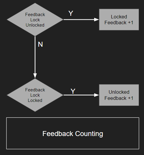
Figure 2 – Lock Feedback Counting
Test Cycle Monitoring
To monitor the testing, I created a dashboard that keeps track of cycles, mismatches and re-syncs. Notice that the total feedback (795) does not equal the total commands (800). This is the missing data that was discussed at the top of the article and is used in the +/- calculation for lock reliability.
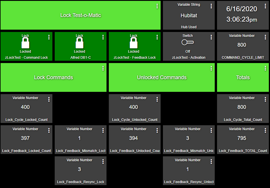
Figure 3 – Test-o-Matic Dashboard
Total Cycles
Total cycles is pretty simple in that every time the hub sends a command to lock or unlock it increments the count. I refer to this as Commands.
Total Feedback
Total Feedback is looking at how many times the lock reported a state change AND how many times the the command side reported a mismatch. Re-sync is not counted in the total feedback, which I’ll explain why later. My logic may be flawed, but it’s what I decided to do.
Error Calculations
When accounting for errors, I debated internally if the Re-sync counts should be included in some way or another. I ultimately decided yes.
Here’s the missed cycle in a nutshell:
- Missed Unlocked Feedback
- Commanded to Lock
- Feedback not received
- Feedback = Unlocked / Command = Locked
- Not detected (can’t be reliably) on current cycle
- Next Cycle (C2)
- Mismatch Detected
- Mismatch Recorded
- Need to sync Feedback and Command
- Feedback = Unlocked / Command = Unlocked
- Mismatch Detected
We know that there was a mismatch, but we don’t know if the lock actually cycled or not. The re-sync could either be turning the lock or not. Again, we just don’t know (unless we’re watching). So when it comes to feedback count, we will never get the feedback for the previous missed cycle. This is not the fault of the current cycle and, in my opinion, must be accounted for. This is why there’s a re-sync count.
So, per Figure 3 above, there were 800 successful cycles that we are absolutely sure about and there were 4 mismatches. Easy math would say that since we tried 800 times our reliability would be 99.2%. But it’s not that simple (in my brain anyway).
If the four re-syncs had actually successfully cycled (which we’ll never know), that would make the success rate 99.5%. And if the four re-syncs had been unsuccessful (again we’ll never know) our success rate would have been 98.9% So, in my opinion, that makes the reliability somewhere between 98.9% and 99.5% OR 99.2% +/- 0.3%.
So that’s it. When you see me, “say a lock has a Command/Feedback Reliability of 94% +/- 2%”, you know how I got there.
Again, it’s not perfect, but it is consistent across all locks I test.
If you have a better way, jump over to the DIY Smart Home Guy Facebook Group and let me know. I’m always interested in being better.
How This Was Accomplished in Hubitat
As of the time of this writing, all of the testing is conducted from a Hubitat hub that has the capability to control a SmartThings hub. This allows me to run tests in Hubitat and SmartThings even though all of the command logic originates in Hubitat. I am currently seeking help moving the same Hubitat logic into SmartThings webCoRE, but need some help. If you would like to volunteer with the webCoRE migration, send me a message on Facebook.
The instructions below assume a certain level of knowledge with Hubitat Rule Machine, Hubitat Global Variables, Hubitat Connectors, and Hubitat Dashboards. I will not be covering those topics here.
Step 1 – Create Global Variables
There are several Global Variables that need to be created to make all of this fit together. Please forgive my inconsistent use of CASE and NAMING. This evolved over time and I wasn’t paying attention. Now I’m too lazy to go back and fix it. You’ll want to clean all of this up if you plan to attempt the project yourself.
| Name | Type | Connector | Default Value |
| LOCK_COMMAND_CYCLE_LIMIT | Number | Variable | 100 |
| LOCK_COMMAND_CYCLE_SECONDS | Number | Variable | 20 |
| LOCK_COUNT_LOCK_DEFAULT | Number | Variable | 0 |
| LOCK_COUNT_UNLOCK_DEFAULT | Number | Variable | 0 |
| Lock_cycle_locked_count | Number | Variable | 0 |
| Lock_cycle_unlocked_count | Number | Variable | 0 |
| Lock_cycle_total_count | Number | Variable | 0 |
| Lock_feedback_Mismatch_Locked | Number | Variable | 0 |
| Lock_feedback_Mismatch_Unocked | Number | Variable | 0 |
| Lock_feedback_TOTAL_count | Number | Variable | 0 |
| Lock_feedback_keypad_used | Boolean | false | |
| Lock_feedback_locked_count | Number | Variable | 0 |
| Lock_feedback_resync_lock | Number | Variable | 0 |
| Lock_feedback_resync_unlock | Number | Variable | 0 |
| Lock_feedback_unlocked_count | Number | Variable | 0 |
| Lock_keypad_TOTAL_count | Number | Variable | 0 |
| Lock_keypad_lastuser | Number | Variable | 0 |
| Lock_keypad_locked_count | Number | Variable | 0 |
| Lock_keypad_unlocked_count | Number | Variable | 0 |
- Connectors allow the variable to be place on a dashboard.
Step 2 – Create Virtual Switches
Virtual switches are used for: 1) starting the automated test; 2) distinguishing between automated testing and manual (keypad) testing; and 3) clearing the variables for the new run.
Lock Test Activation – used to initiate the automated test. Create the virtual switch with ‘Enable auto off’ = Disabled.
Lock Test Disable Manual Counts – used to distinguish between automated testing and manual testing. Status errors are handled differently between these operating modes. Create the virtual switch with ‘Enable auto off’ = Disabled.
Lock Test Clear Variables – used to clear the variables for both manual and automated testing. Create the virtual switch with ‘Enable auto off’ = 2s.
Step 3 – Create Virtual Locks
Due to the fact that I’m reusing this for multiple locks and I need a way to quickly change locks in and out without compromising my core Command and Feedback logic (described in more detail below) it was necessary to create virtual locks.
zCommandLock is the virtual lock that sends commands to the lock being tested.
zFeedbackLock is the virtual lock that receives feedback from the lock being tested. This lock provides an additional advantage in the program. Some locks (mostly Zigbee locks I’ve tested) send the feedback multiple times (usually twice). Even though the test lock sends multiple status updates, the zFeedbackLock only registers the change once thus discarding erroneous status updates. It purifies the count for lack of better ways of saying it.
Step 4 – Create the Lock Command Manager
The test lock then interacts with the main code through a Command Manager and a Feedback Manager (both are rules in Hubitat Rule Machine).
The figure below is the Hubitat rule the Lock Command Manager. When adding in a lock to be tested, there are two actions to modify. In this case those related to Lab HE43 Yale Assure SL. Triggering will be covered later in the article.
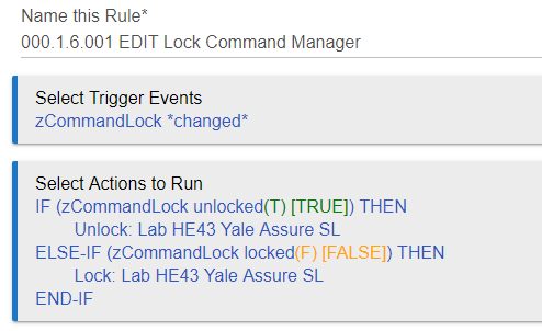
When the Lock Cycle Test – Send Command Rule runs, it controls zCommandLock, which in turn uses this rule to control the lock being tested.
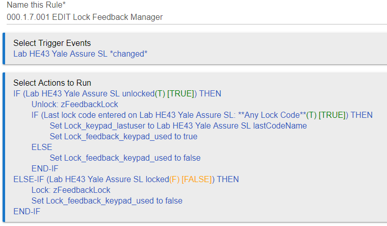
Step 5 – Create the Lock Feedback Manager
The figure below is the Lock Feedback Manager. When adding a lock to be tested there are three aspects to be changed: 1) the trigger must be the test lock; 2) the IF Conditions must be the test lock; and 3) the Lock_keypad_lastuser variable must be set by the lastCodeName attribute of the test lock. A full list of variable can be found at the bottom of the article.
Step 6 – Create the Clear Variables Rule
To make sure that everything is ready for the next run, we’ll need to clear the counts from the previous run. The image below shows the rule that clears everything and is activated by the Lock Test Clear Variable virtual switch created in Step 2. Remember that when creating this switch, set it to automatically turn off after two seconds. This saves you from having to turn if off manually.
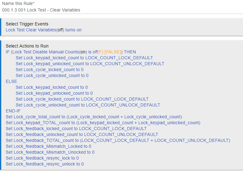
For my purposes I have the ability to seed default variables. Since I make videos, I have had times where I’ve neglected to record the results and needed a way to go back in make the system simulate the results. This is here only for production purposes. While all my published results are indeed real, this helps me show those results in the video in the event that I missed the shot during testing.
Step 7 – Setup the Lock Cycle Test Send Command
Okay, this is where it gets serious. The following image is the rule that sends commands to the lock. It also has the mismatch error detection (since it can’t be performed on the feedback side). Notes are below the image.
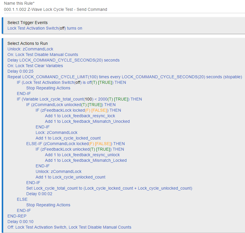
- The routine is activated (triggered) when the Lock Test Activation virtual switch is turned on and continues to run until either a) the switch is turned of, or b) the desired cycles have been reached.
- Before the cycle commands start, the following actions are performed:
- Unlock zCommandLock – this resets the lock to ensure everything is properly set.
- Turn on the Lock Test Disable Manual Counts virtual switch – this let’s the system know it’s in auto mode and does not increment manual or keypad counts.
- I put in a delay to make sure everything cycles. I use the LOCK_COMMAND_CYCLE_SECONDS variable for the delay.
- Turn on the Lock Test Clear Variable virtual switch to clear the variables. This switch turns off automatically after 2 seconds.
- One more delay to make sure all variables clear and make sure I’m ready to view the results.
- The Repeat block is set entirely with variables. I will show later show these are set on the Dashboard. It’s important to make sure the Repeat action is defined as stoppable (which is misspelled in the Hubitat app).
- The first Conditional block looks to see if the Lock Test Activation switch has been turned off. If so, the Repeat action aborts.
- The next Conditional action determines if the total cycle count is less than 2000. This is probably useless as it was intended to stop a runaway Repeat action. After several iterations of the rule, this is no longer needed. I need to update this to match against the LOCK_COMMAND_CYCLE_LIMIT variable. Too lazy.
- The real meat is the third Conditional action. This is where the command to send is evaluated and then the mismatch is evaluated.
- Inside each command statement the appropriate cycle count variable is updated. If errors are detected, the mismatch and resync variables are updated.
- At the end of the evaluation, the total counts are updated (Set Lock_cycle_total_count to (Lock_cycle_locked_count + Lock_cycle_unlocked_count)).
- Delay added for giggles to make sure the rule has a chance to do the math. Unnecessary, but I have it there for giggles.
- At the end I added another delay to do math. Again, not necessary, but I put there when I was troubleshooting a different problem. Why didn’t I take it out? Too lazy.
- Finally, the rule turns off the Lock Test Activation Switch and the the Lock Test Disable Manual Counts switch.
All feedback is detected in the next rule.
Step 8 – Setup the Lock Cycle Test Feedback Rule
This rule runs completely independent of the Command rule (Step 7). It is triggered by any detected change in status sent from the zFeedbackLock, which is triggered from the test lock in the Feedback Manager (Step 5). The image below describes the rule. Notes about the rule are outlined below the image.
- The first Conditional action determines if the event received was an unlocked or locked status. Each case increments the appropriate feedback value.
- The Conditional action inside each event then tests to see if the Lock Test Disable Manual Counts virtual switch is off. If so, it counts the feedback as a manual event.
- If manual the keypad total count is incremented.
- In either case the feedback total count is incremented.
- The last user is simply set to Locked.
- On the unlock side, if manual is detected (switch setting), the last user variable collects the user from the variable that is set in the Feedback Controller. This allows me to verify the lock codes are sending correctly. It’s all manual verification for now. Thinking of ways to make this more automated.
- After the first Conditional action we do a bunch of variable math to make sure everything is viewable from the dashboard.
Step 9 – Assemble the Dashboards
You can assemble the Dashboards in any way you see fit. The image below is how mine is configured (or was configured). I change this around all the time to better understand the results at a glance.
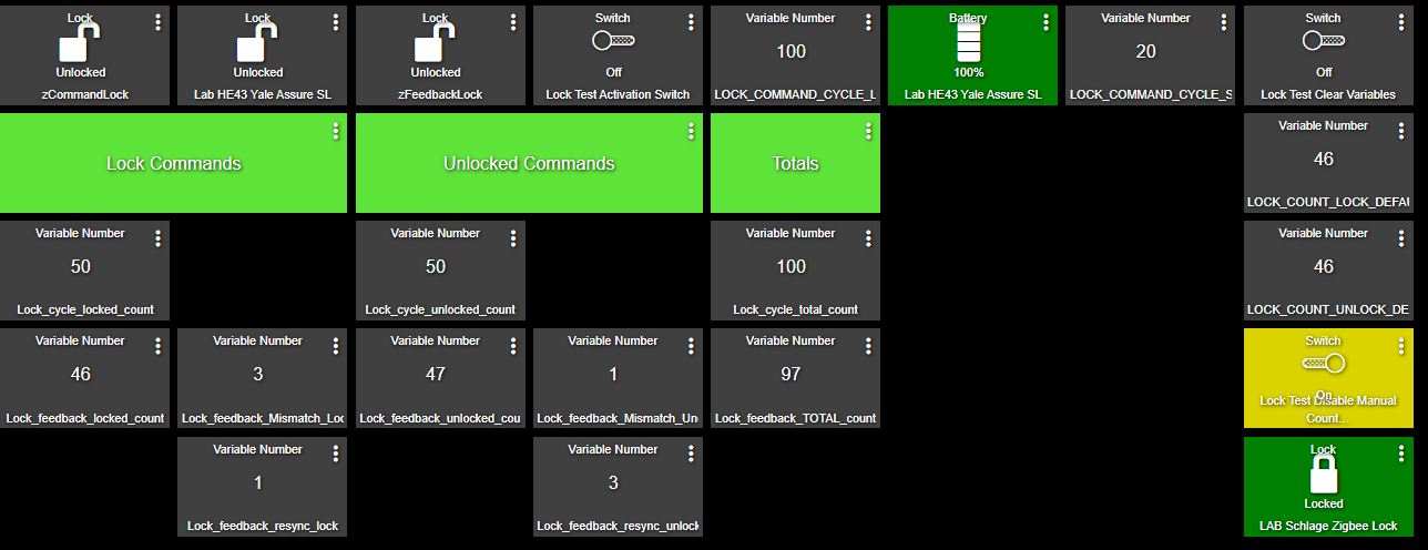
Row 1
The top row displays the status of the Command lock, the Test lock and the Feedback lock. Items on this row (left to right):
- Command Lock (virtual)
- Test Lock (physical)
- Feedback Lock (virtual)
- Lock Test Activation Switch (virtual)
- LOCK_COMMAND_CYCLE_LIMIT (variable) – set this to determine how many cycles to test the lock. It is the total locks and unlocks.
- Test Lock battery level (physical) – optional
- LOCK_COMMAND_CYCLE_SECONDS (variable) – set this to tell how long the Command rule should wait in between cycles. I usually set this between 15 – 20 seconds.
- Lock Test Clear Variables Switch (virtual)
Row 3
- Lock Cycle Locked Count (variable) – how many times the lock cycle command was issued by the hub.
- unused
- Lock Cycle Unlocked Count (variable) – how many times the unlocked cycle command was issued by the hub.
- unused
- Lock Cycle Total Count (variable) – the total Lock and Unlock commands sent by the hub.
Row 4
- Lock Feedback Locked Count (variable) – how many times the locked status was received by the hub.
- Lock Feedback Mismatch Locked (variable) – how many times there was a mismatch when the lock command was issued and the Test Lock continued to report unlocked.
- Lock Feedback Unlocked Count (variable) – how many times the unlocked status was received by the hub.
- Lock Feedback Mismatch Unlocked (variable) – how many times there was a mismatch when the unlock command was issued and the Test Lock continued to report locked.
- Lock Feedback Total Count (variable) – the total Lock and Unlock commands sent by the hub + the mismatch count. Does not include the Resync Count.
Row 5
- unused
- Lock Feedback Resync Locked – how many times the Command Rule sent the command for locked AFTER a mismatch was detected. This number should always equal UNLOCKED Mismatch count.
- unused
- Lock Feedback Resync Unlocked – how many times the Command Rule sent the command for unlocked AFTER a mismatch was detected. This number should always equal LOCKED Mismatch count.
See the Error Calculations section for more information as to how this is used and why.
Step 10 – Setting the Lock Command Cycle Limit Variable
It is possible to set this value directly from the dashboard. But first, let’s cover setting up the dashboard widget. Remember, when you set up the variables in Step 1 you created some of them as Connectors. This allows them to be placed on a Dashboard.
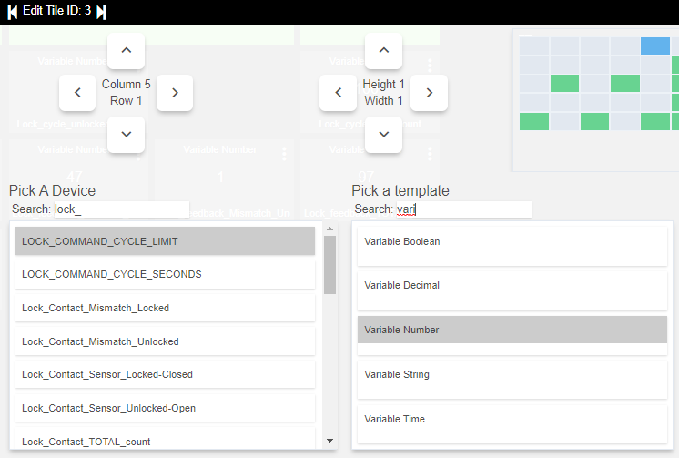
- Pick A Device – LOCK_COMMAND_CYCLE_LIMIT (or other variable to be added)
- Pick a template – Variable Number
The variable is now on the dashboard.
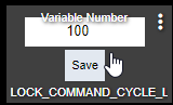
When you click on the variable, the field will become editable. Enter your desired value and click Save.
Step 11 – Run the Test
Turn on the Lock Test Activation Switch and you’re off and running.
Have fun! And, let me know how it went over on the DIY Smart Home Guy Facebook Group.
END